
- Expected gross line load verified against the Structure-Anchored Working Load Limit 45 kg.
- Rope length and rope route suitable for the Structure-Anchored method.
- Suitable anchor point available.
- Rope path free from sharp edges.
- Required PPE worn.
Free of damage
No knots, twists, rope protection elements
Lifting path free of sharp edges or rope-unfriendly obstacles
Load in working range subject to rope length and routing
No action in the Pilot Phase,
else Rope Pressure Setting to match Rope
Assure stable hoisting without slip
Check Rope Pressure Table
Set the drill to reverse and drilling mode, do not use hammer mode. Always press the trigger gradually during operation.
Drill speed range less then 1800 rpm
1/4 inch Socket Adapter installed
Full battery
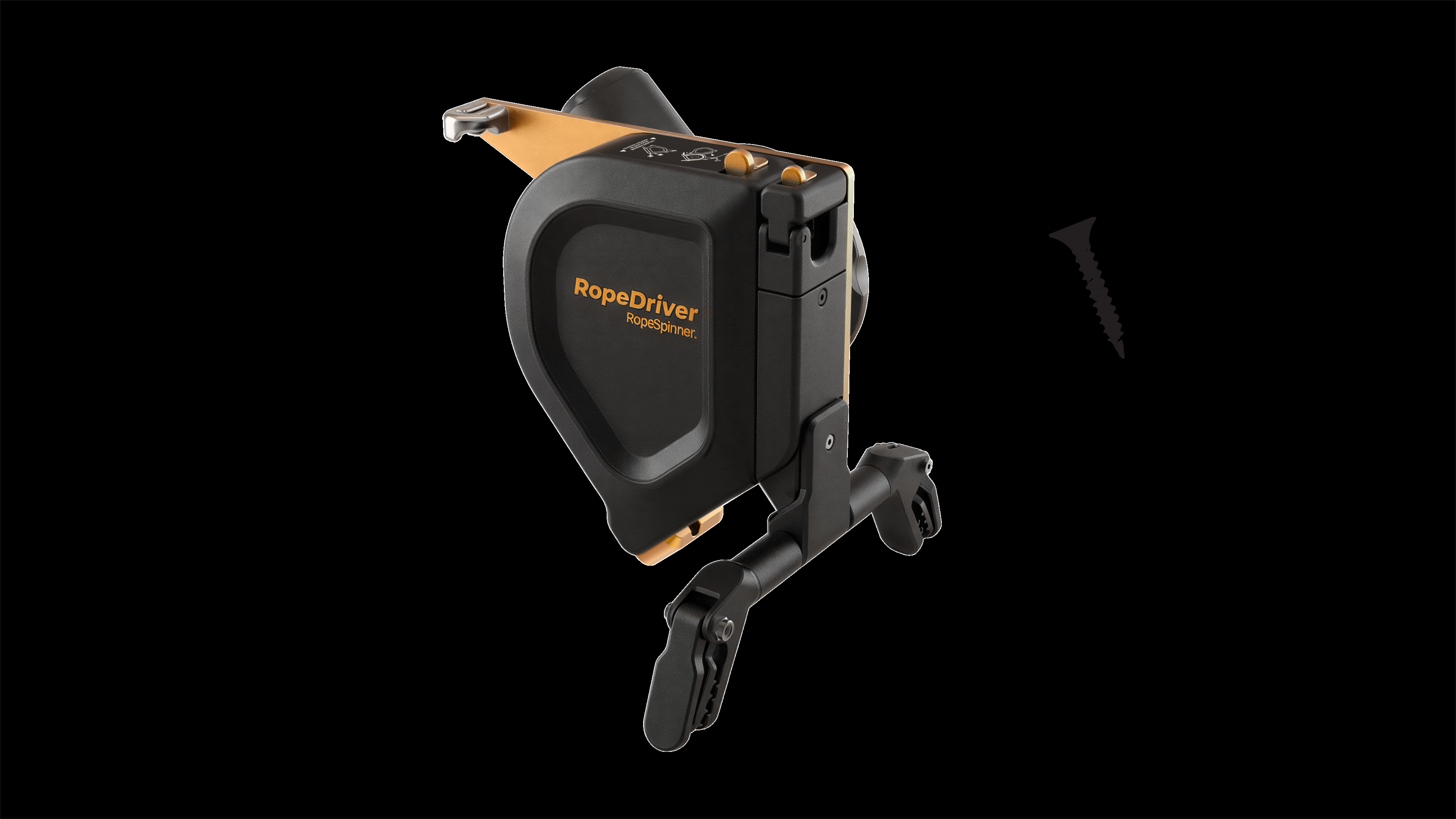
Connect BagFrame to RopeDriver
Have rope bag ready near workspot
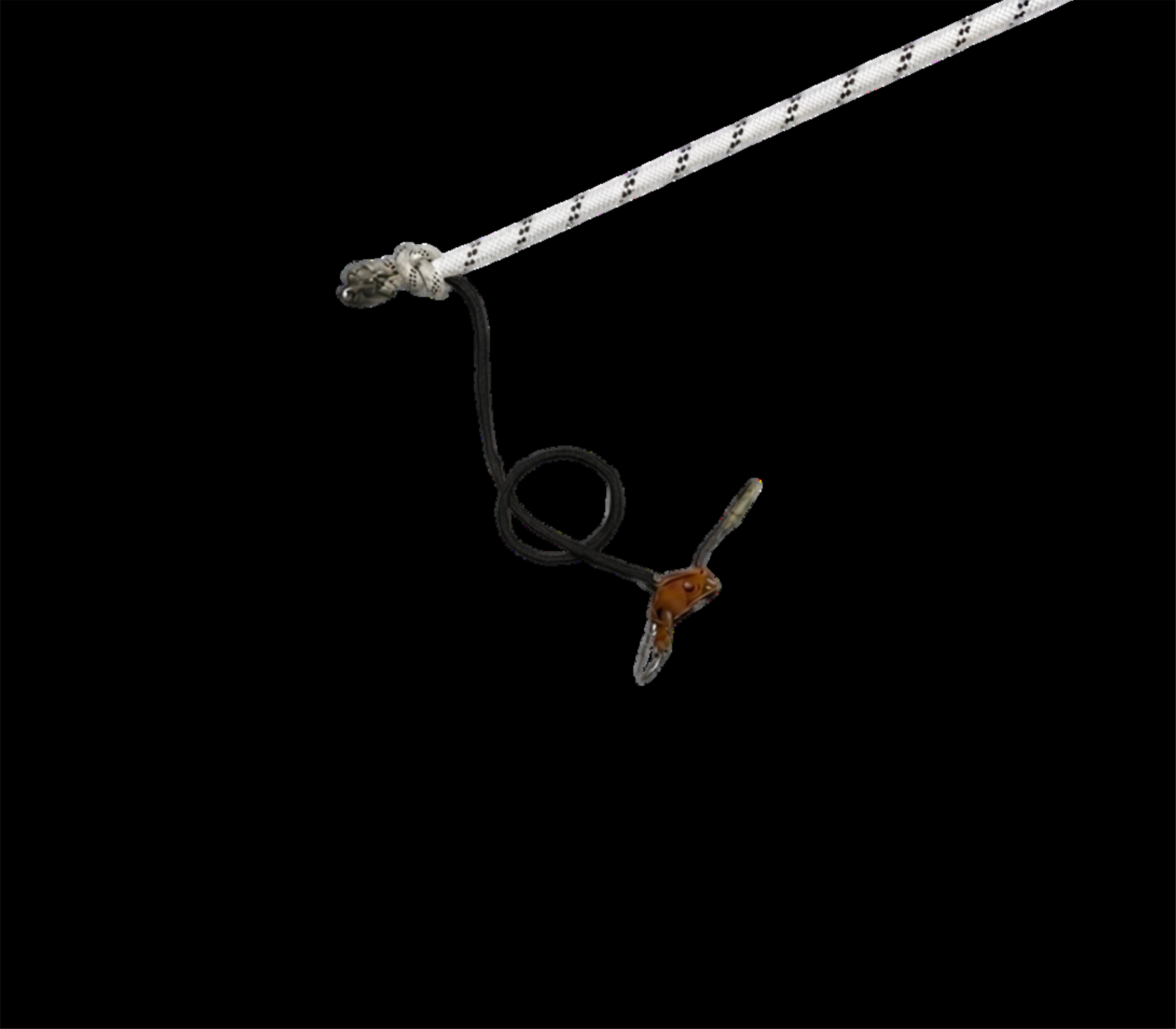
Connect the adjustable lanyard (grillon) to the ground structure
prefer the same anchor-point as the rope
Select RopeSpinner connection point
somewhat above later work position
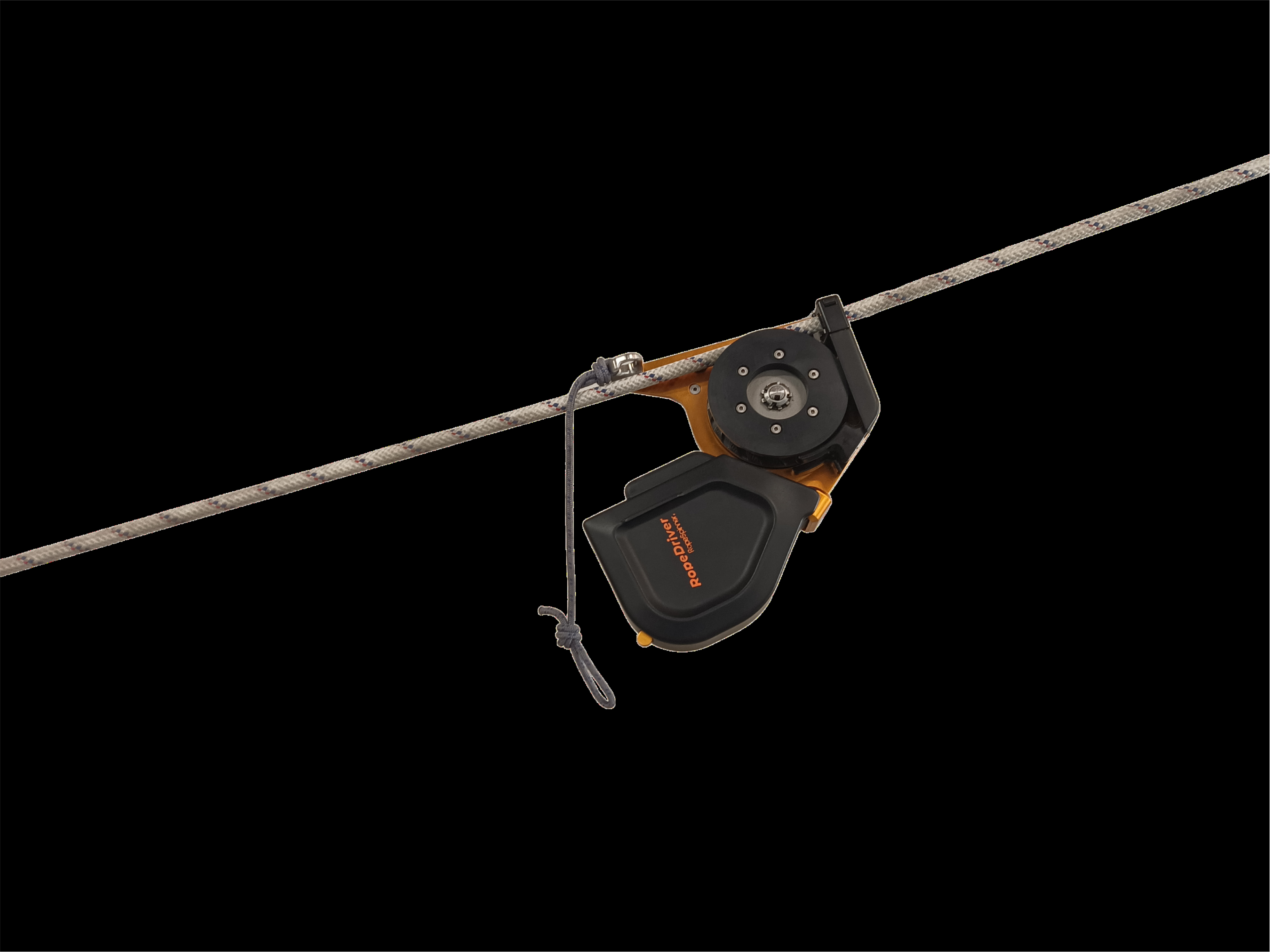
Selected best position to connect
Open Cover and Rope Latch
Guide rope through the Rope Entry Port
Along the Rope Clamp against the spring pressure
Close the Rope Latch
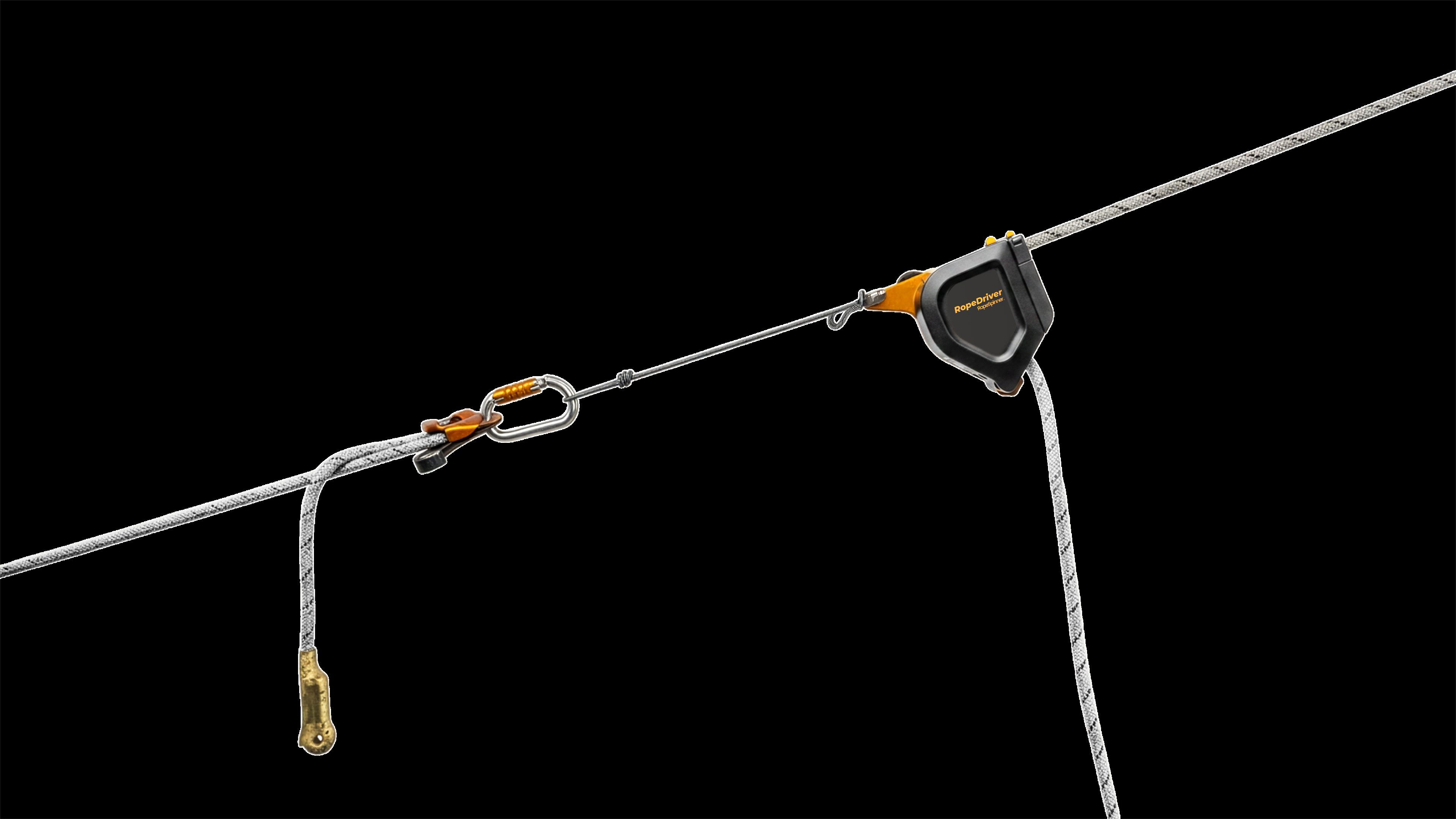
Lean the Anchor Ring on the rope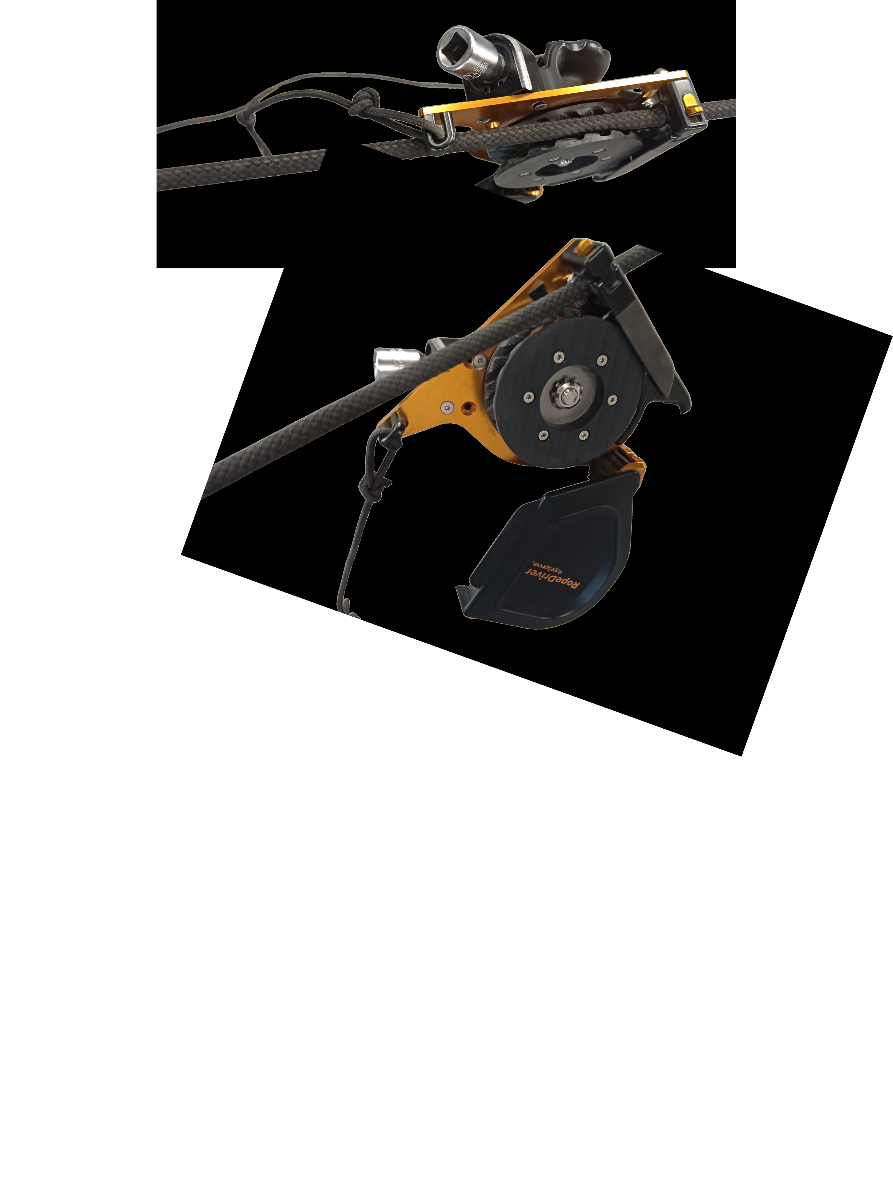
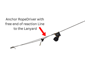
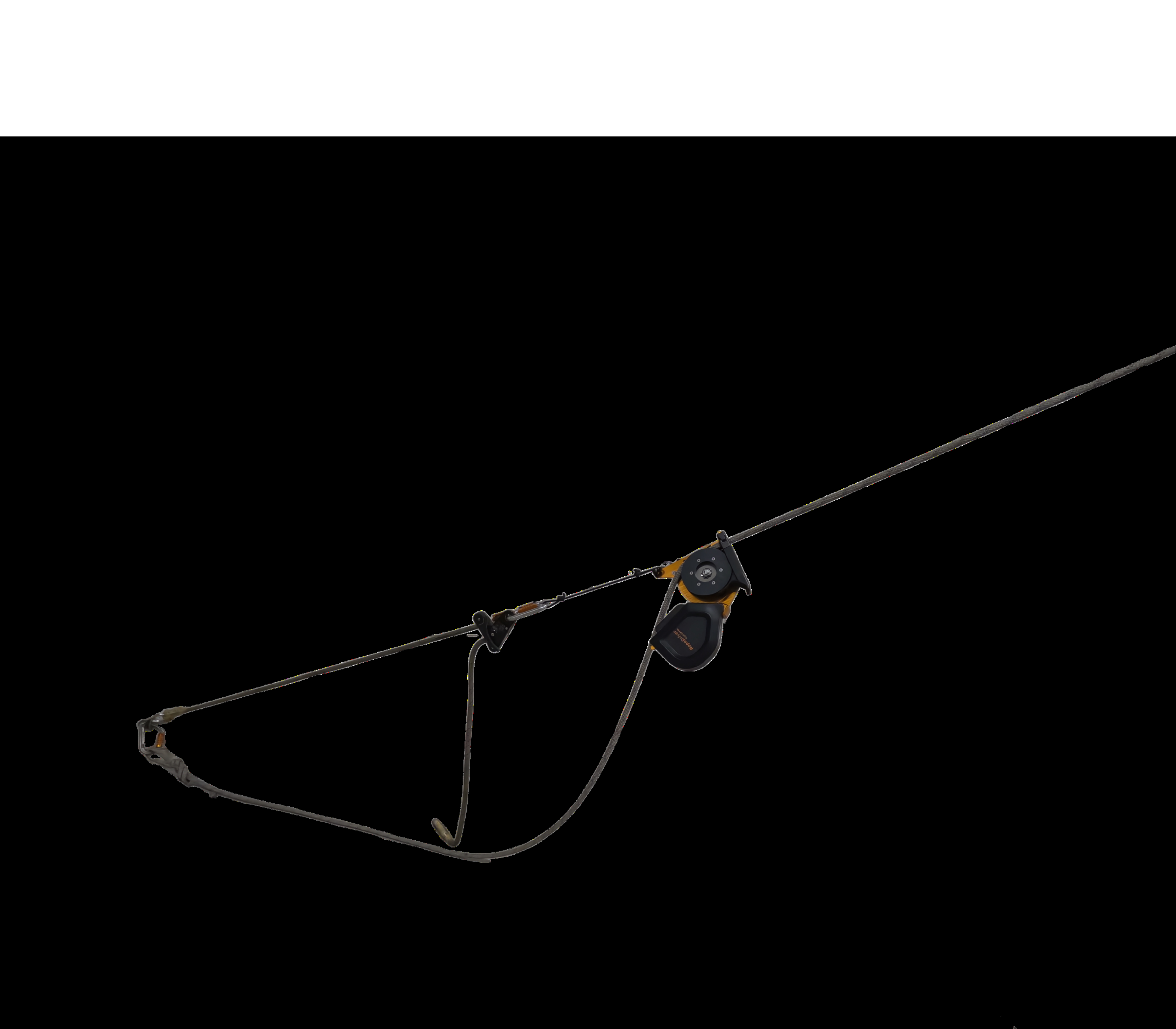
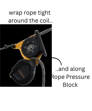
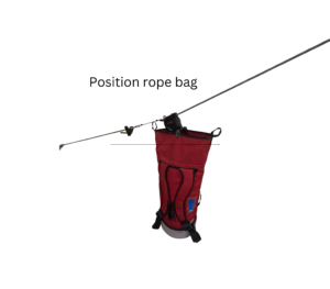
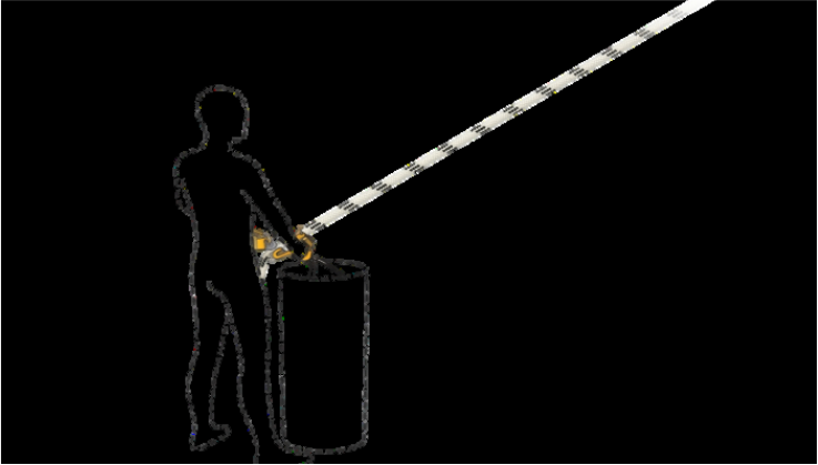
Where practical, connect the rope bag to the RopeDriver using the BagFrame. A stable, self-supporting bag may also be placed directly underneath.
Stand on the left side of the rope
Hold RopeDriver handle firmly with left hand
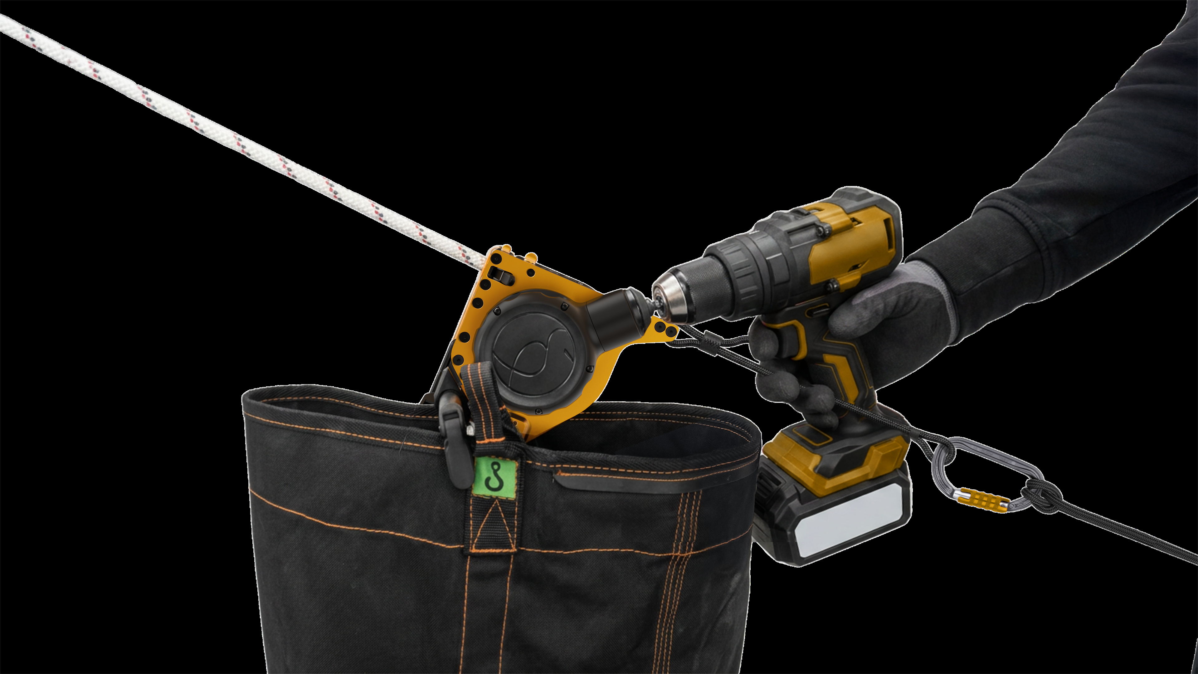
Mount the drill onto the socket with your right hand. Position the drill handle to the right of the reaction line to restrain the reaction torque.
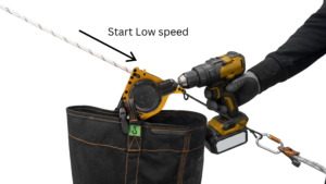
Start low-speed for rope to settle in coil
Verify stable hoisting without slip
Let system stabilize before increasing speed
In case uncontrolled slip stop immediately
and TROUBLESHOOT
When rotation stable gradual speed increase
Maintain visual control of the rope
In case of slip stop immediately
and TROUBLESHOOT
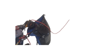
Stop hoisting slow and well before end of rope
Rope only to reach the system
No labels, loops, or protective elements
No rope ending to get stuck inside
- Expected gross line load verified against the Harness-Anchored Working Load Limit 25 kg.
- Rope length and rope route suitable for the Harness-Anchored method.
- Suitable anchor point available.
- Rope path free from sharp edges.
- Required PPE worn.
Free of damage
No knots, twists, rope protection elements
Lifting path free of sharp edges or rope-unfriendly obstacles
Load in working range subject to rope length and routing
No action in Pilot Phase, else
Rope Pressure Setting to match rope
Assure stable hoisting without slip
Check Rope Pressure Table
Set the drill to reverse and drilling mode, do not use hammer mode. Always press the trigger gradually during operation.
Install 1/4 inch socket adapter
Full battery
Optionally connect BagFrame to RopeDriver
Have bag ready near workspot
Connect RopeDriver with the free end of the reaction line to your harness connection point
Secure yourself
Stand on left side of the rope
Open Cover
Pick up rope with your right hand
Create slight slack between your hand and the rope anchoring point
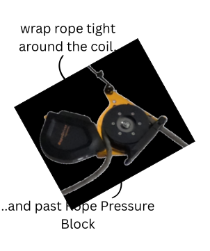 Close the Cover
Hold RopeDriver handle with left hand
Mount the drill with right hand
Start low-speed for rope to settle in coil
Verify stable hoisting without slip
Let system stabilize before increasing speed
In case uncontrolled slip stop immediately
and TROUBLESHOOT
When rotation stable gradual speed increase
Maintain visual control of the rope
In case of slip stop immediately
and TROUBLESHOOT
Stop hoisting slow and well before end of rope
Rope only to reach the system
No labels, loops, or protective elements
No rope ending to get stuck inside
Free of damage
No knots, twists, rope protection elements
Lifting path free of sharp edges or rope-unfriendly obstacles
Load in working range subject to rope length and routing
No action in Pilot Phase, else
Rope Pressure Setting to match rope
Assure no slip
Less critical as no load
Check Rope Pressure Table
Set the drill to reverse and slip clutch mode, do not use hammer mode. Always press the trigger gradually during operation.
Install 1/4 inch socket adapter
Full battery
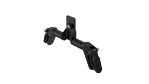
Apply BagFrame if convenient
Secure yourself
Stand on left side of the rope
Hold RopeDriver in left hand
Open Coils Cap
Pick up rope with your right hand
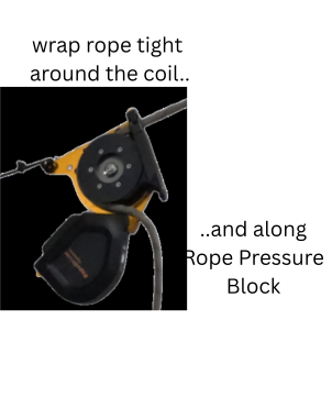
Close the Coil Cap
Hold RopeDriver handle with left hand
Mount the drill with right hand
Start low-speed for rope to settle in coil
Verify stable hoisting without slip
Let system stabilize before increasing speed
In case uncontrolled slip stop immediately
and TROUBLESHOOT
When rotation stable gradual speed increase
Maintain visual control of the rope
In case of slip stop immediately
and TROUBLESHOOT
Stop hoisting well before end of rope
Rope only to reach the system
No labels, loops, or protective elements
No rope ending to get stuck inside
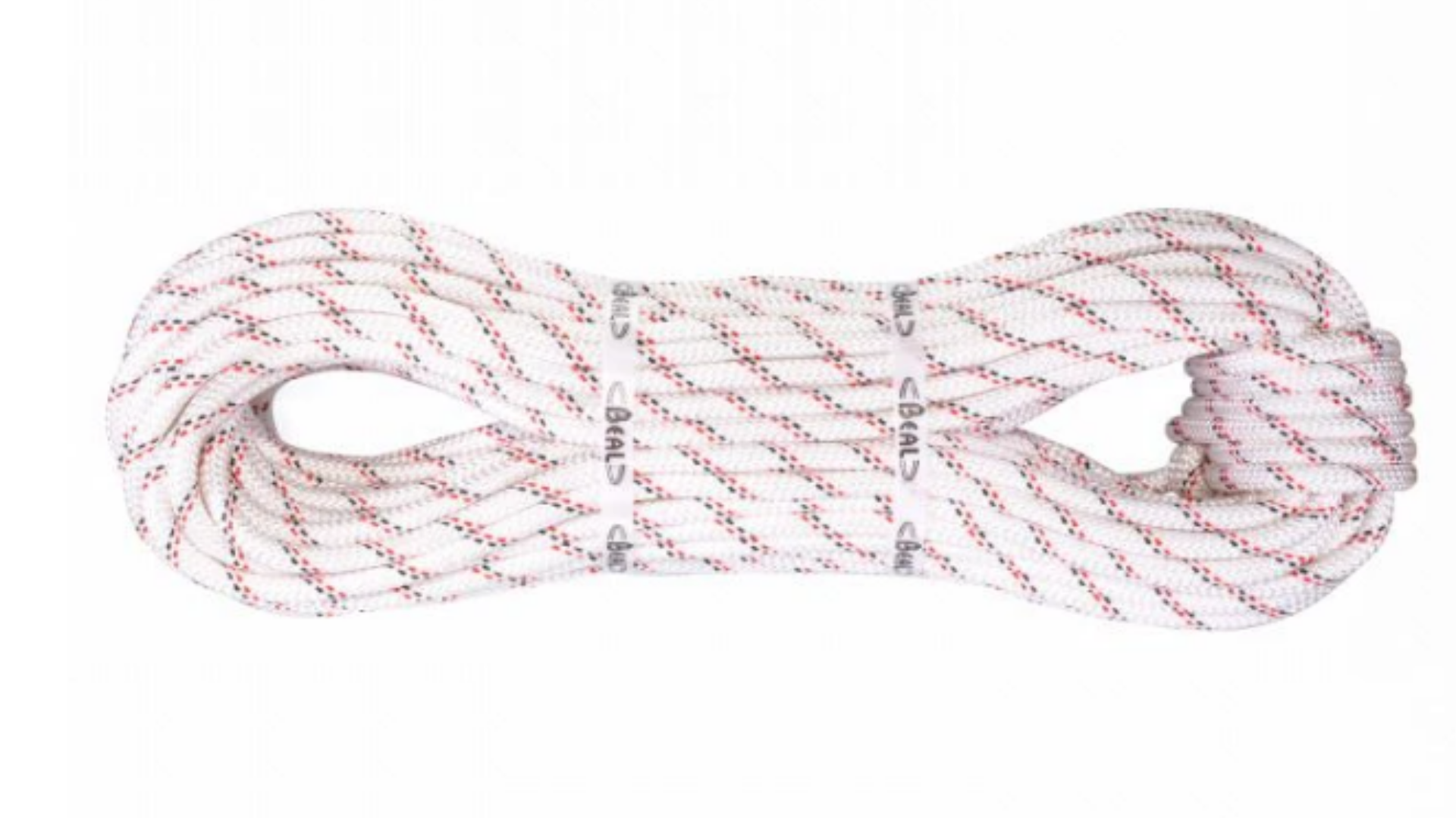
- Model: Beal Industrie 10,5 mm
- Diameter: 10,5 mm
- Standard: EN 1891 Type A
- Relatively light and flexible
- Grip potential lower
Rope Pressure Setting = Contact RopeSpinner Team
Subject to Age, Wear and Moisture
- Model: Beal Industrie 11,0 mm
- Diameter: 11,0 mm
- Standard: EN 1891 Type A
- Most common version
- Grip potential medium
Rope Pressure Setting = 5
Subject to rope Age, Wear and Moisture
- Model: Beal Industry 11,5 mm
- Diameter: 11,5 mm
- Standard: EN 1891 Type A
- Higher abrasion resistance
- Slightly heavier and stiffer
- Grip potential higher
Rope Pressure Setting = Contact RopeSpinner Team
Subject to rope Age, Wear and Moisture
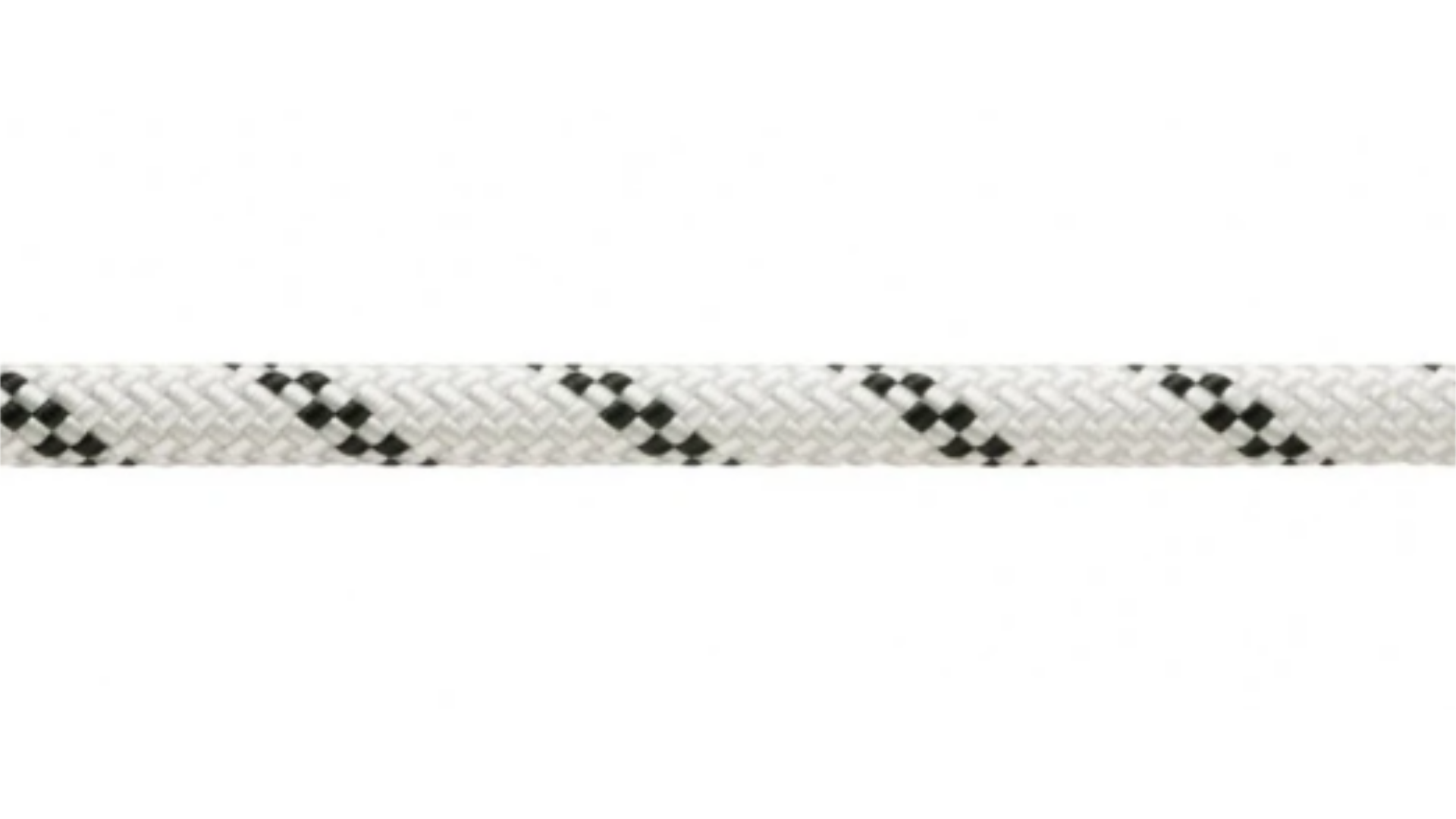
- Model: Petzl Axis 11,0 mm
- Diameter: 11,0 mm
- Standard: EN 1891 Type A
- Higher abrasion resistance
- Slightly heavier and stiffer
- Grip potential higher
Rope Pressure Setting = 5
Subject to rope Age, Wear and Moisture
- Model: Petzl parallel 10,5 mm
- Diameter: 10,5 mm
- Standard: EN 1891 Type A
- Higher abrasion resistance
- Slightly lighter and more flexible
- Grip potential lower
Rope Pressure Setting = Contact RopeSpinner Team
Subject to rope Age, Wear and Moisture
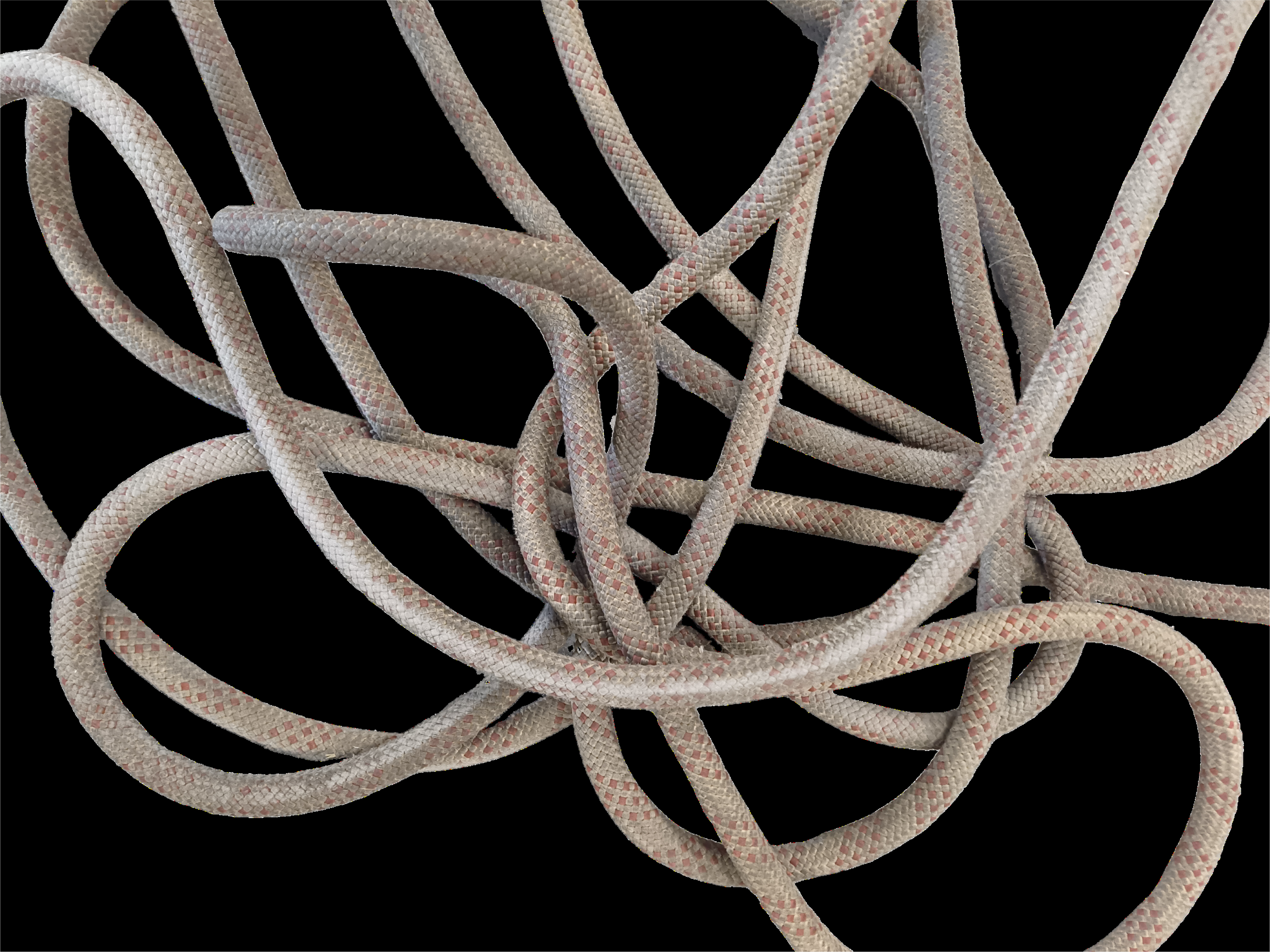
- Model: <model?>
- Diameter: <?>
- Standard: <standard>
- <Characteristics>
- <Characteristics>
- Grip potential <grip potential?>
Rope Pressure Setting = 5
Subject to rope Age, Wear and Moisture
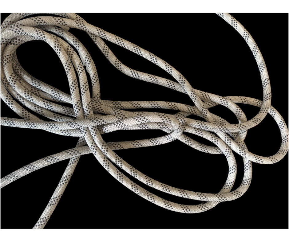
- Model: <model?>
- Diameter: <?>
- Standard: <standard>
- <Characteristics>
- <Characteristics>
- Grip potential <grip potential?>
Rope Pressure Setting = 5
Subject to rope Age, Wear and Moisture
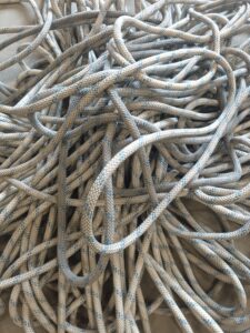
- Model: English braids <model?>
- Diameter: <?>
- Standard: <standard>
- <Characteristics>
- <Characteristics>
- Grip potential <grip potential?>
Rope Pressure Setting = 5
Subject to rope Age, Wear and Moisture
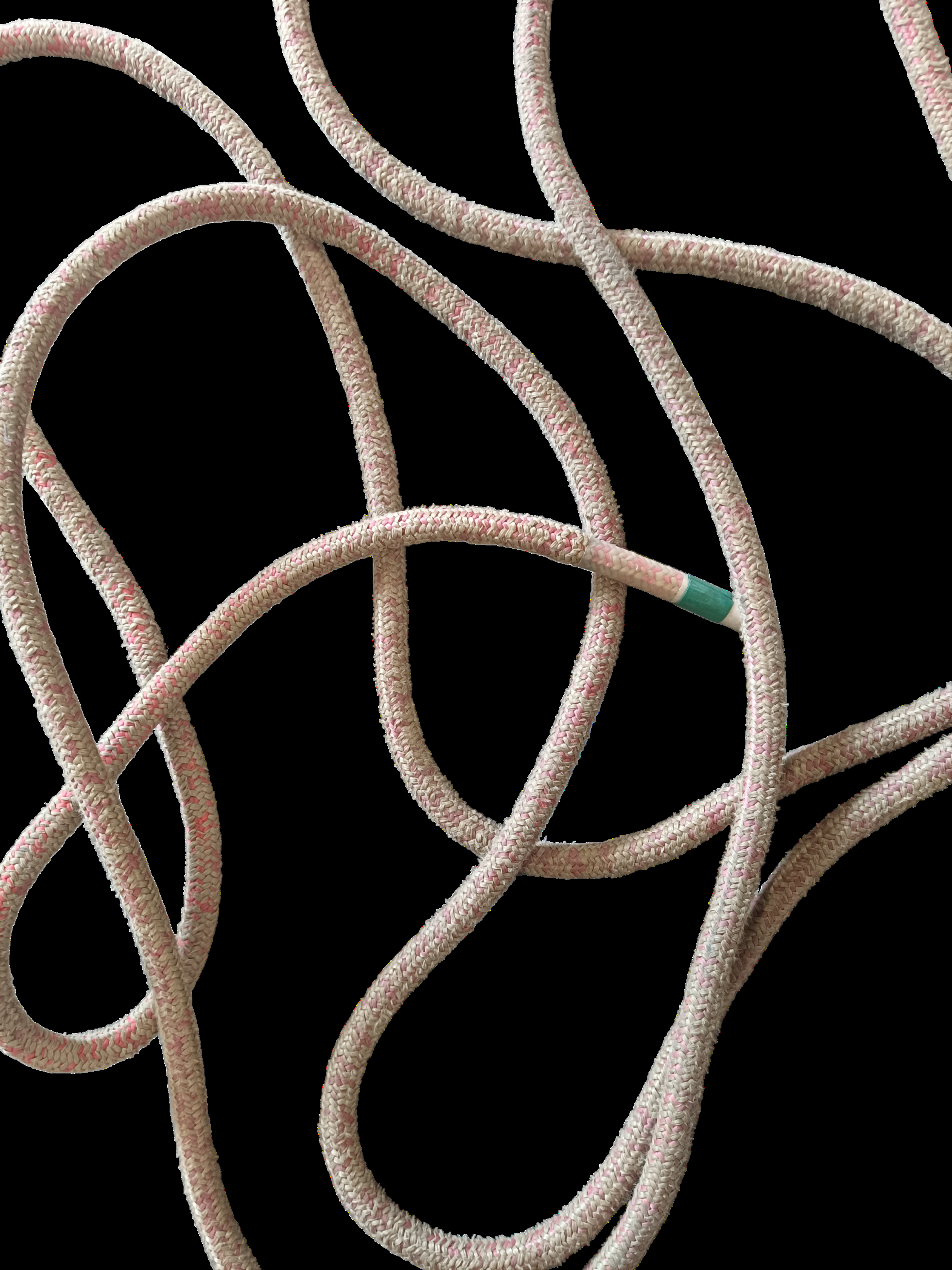
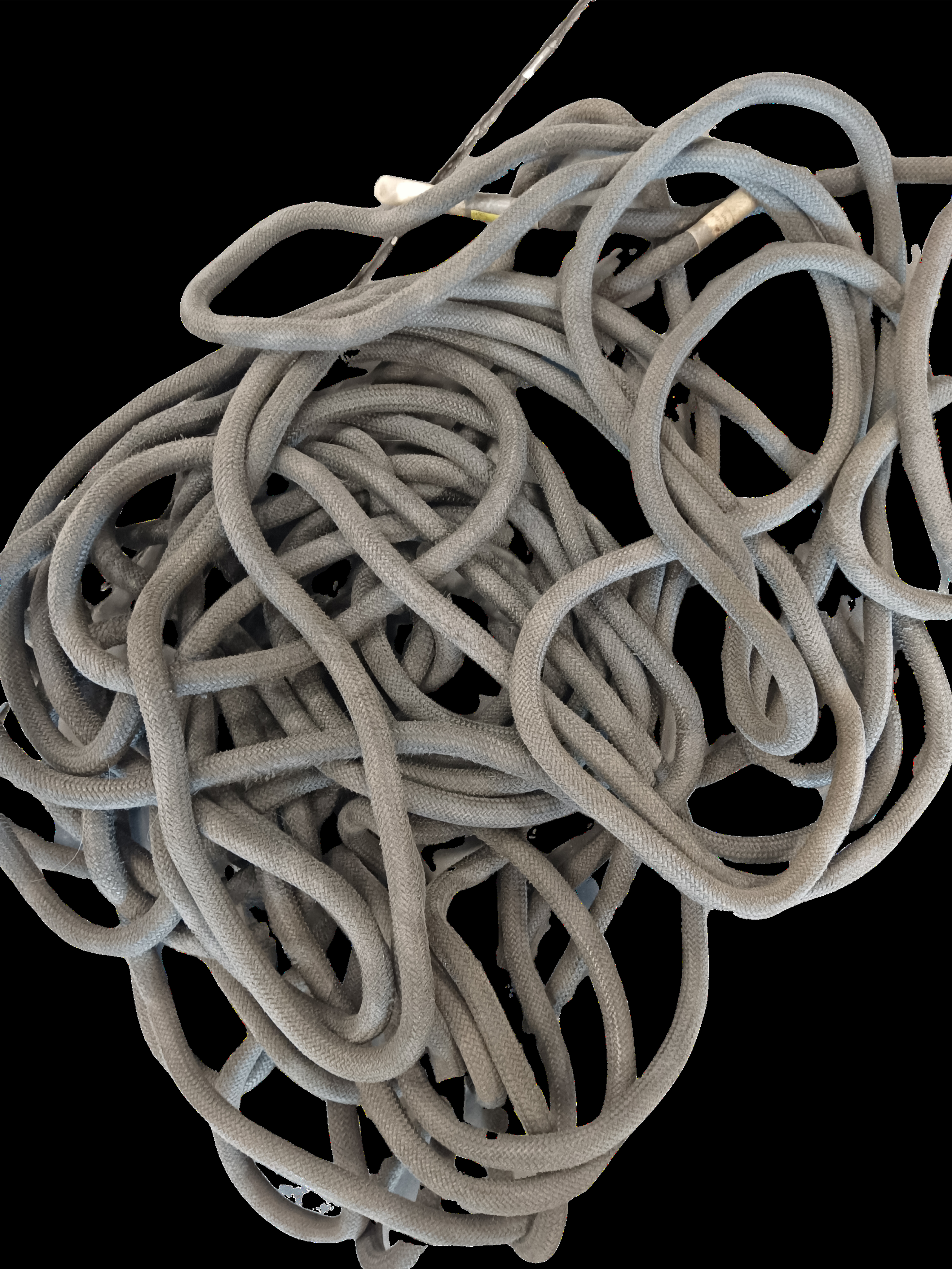
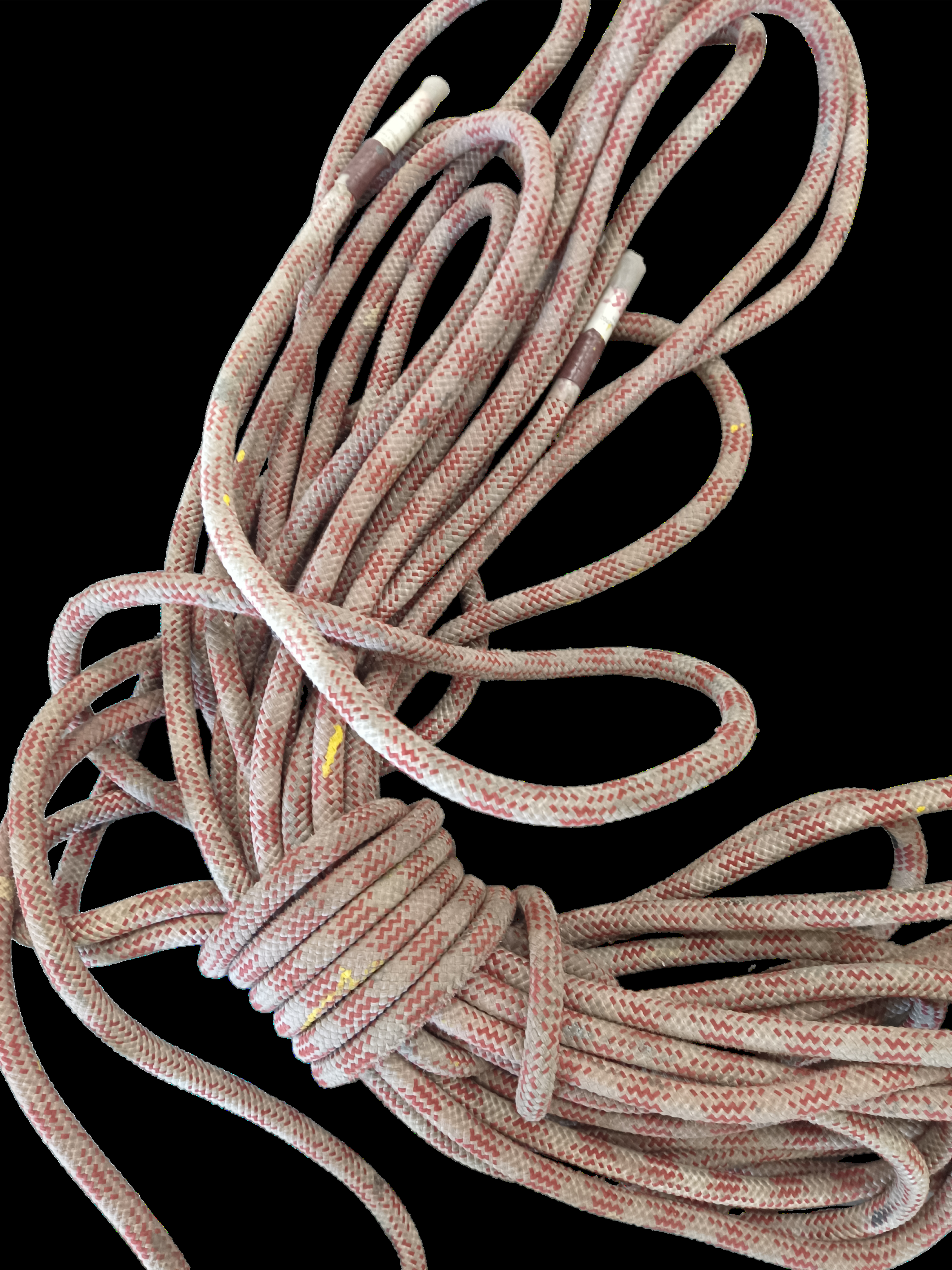
- Model: <model?>
- Diameter: <?>
- Standard: <standard>
- <Characteristics>
- <Characteristics>
- Grip potential <grip potential?>
Rope Pressure Setting = 4
Subject to rope Age, Wear and Moisture
- Model: <model?>
- Diameter: <?>
- Standard: <standard>
- <Characteristics>
- <Characteristics>
- Grip potential <grip potential?>
Rope Pressure Setting = 4
Subject to rope Age, Wear and Moisture
- Model: <model?>
- Diameter: <?>
- Standard: <standard>
- <Characteristics>
- <Characteristics>
- Grip potential <grip potential?>
Rope Pressure Setting = Contact RopeSpinner Team
Subject to rope Age, Wear and Moisture
We'll be happy to help you find the optimal Rope Pressure Setting.
Please complete all fields in the web form.